Building a TrainWreck(TM)-inspired Ceriatone Express (ion) — Part 4
by Mark ~ May 18th, 2008. Filed under: Amplifiers.Wiring up the Power Supply
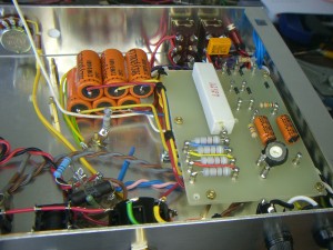
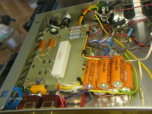
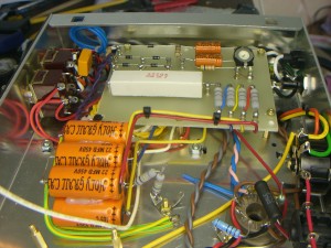
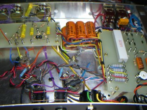
The trickiest part of this project is probably the installation of the power supply board and the filter capacitors. Careful consideration must be given to terminating the various grounds and some care in routing the DC voltages as well. The published layouts provide a good guide and hopefully the high resolution versions of these pictures (click on the picture) will help some more.
I used a hot-glue gun to bond the capacitors together and attach them to the chassis. Others swear that you have to use silicone and worry that the chassis interior may get hot enough to melt or at least soften the hot-glue.
One of the changes I made was to short the bias wiper to the unused leg of the potentiometer in order to ensure that an intermittent wiper wouldn’t open circuit the bias pot completely.
Mounting Components and Wiring the Power Tube Sockets
You were half finished when you hooked up the output transformer and heater wires. The remainder of the power tube wiring is straight forward.
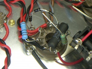
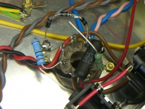
A spare tube pin is used to mount the screen resistor and the screen supply, direct from the power board, is daisy-chained to that pin on both power tube sockets.
I found a couple of precision 1-ohm resistors in my kit so I wired up the cathode and suppressor to ground on each tube through a 1-ohm resistor that is useful for checking and setting the bias.
The little stack of diodes is used to protect against fly-back voltages and supposedly keep a shorted tube from taking out the output transformer… a safety modification Ken used to do in his repair business.
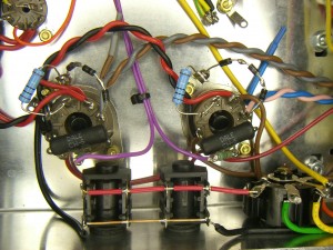
The grid resistors are mounted ‘flying’ off of the grid pin on the tube socket… keep grid resistors close to the pin. The purple wires shown above are the two phased output from the PI tube. Keep the two PI wires symmetrical at the tube so that you can easily swap them if you get positive feedback (squealing) when you first power up. There is a 50% chance of feedback because apparently the transformers aren’t wired with the phase consistent.


