Building a Ceriatone Expression — Part 2
by Mark ~ May 7th, 2008. Filed under: Amplifiers.A lot has happened on the AmpGarage Trainwreck Discussion in the 1+ years since I originally built my Ceriatone. DrHulsey had a thread in which he shared his cleaned up schematic (last update: March, 2008)… finally a schematic that completely aligns with Francesca… here is the DrHulsey Schematic Thread. In this thread is also a layout that DrHulsey derived from Richie’s corrections to the original Ceriatone layout.
With the latest contributions you have a really good set of reference materials if you want to make your clone close to the original… starting with the composite photograph of Francesca’s layout, a clean schematic and finally a checked-out layout diagram.
Mechanical mounting of components
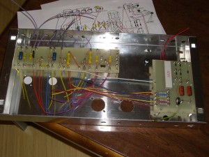
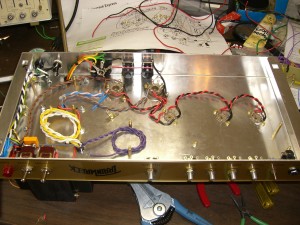
The next phase of the Expression project is to do all the mechanical mounting, with the exception of the turret boards, and wire the AC… power cord, fuse, switches, pilot light, transformers, speaker connectors and OT primary connections to the power tubes. We will also dry-fit the turret boards to make sure that all the mounting studs are positioned properly… I had a minor problem with one of the power-supply board mounting studs in my build and had to use the tolerances of all the other studs to accomodate the slight hole alignment problem.
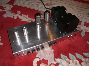
All screws and nuts (or stand-offs in place of nuts) should have lock washers on the nut side… there will be a lot of vibration as part of normal operation of the amplifier and you don’t want something coming loose in an inaccessible location of the chassis after assembly. The transformers are mounted with washers under the screw head to ensure ample coverage of the slotted transformer mounting tabs and locking nuts for security. The potentiometers need the internal nut adjusted for the correct thread depth to accomodate the lock-washer, chassis thickness, faceplate thickness and exterior nut.
Power Transformer and AC Wiring
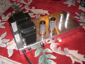
When mounting the transformers, make sure that plastic grommets are installed into the holes to route the transformer leads through. The power transformer is mounted so that the secondary wires come out the inner-most grommet in the chassis.
I got the following information from Nik on the Power Transformer:
Primary:
- 0 (neutral) = black
- 120VAC = orange
- 100VAC = blue (Japan)
- Shield = Green stripe (grounded to chassis)
Secondary:
- 3.15V - brown
- 0 - grey (Filament CT, ground this one)
- 3.15 - brown
- 290V - purple, rated at 150mA per side (300mA)
- 260 - white (for liverpool)
- 0 - grey (HT CT, grounded)
- 260 - white (for liverpool)
- 290 - purple
- 5 Yellow (not used)
- 0 Yellow (not used)
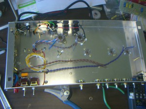
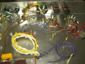
Pairs of wires should be tightly and evenly twisted together to minimize the potential of hum. In the case of the power transformer, the yellows, whites and purples on the secondary are twisted together and the browns from the primary wiring side are twisted together. Yellows and whites aren’t used… any unused wires should be taped (or heat-shrink on the ends of the wires), coiled and stowed out of the way. I created coils that would fit under the power supply board for the unused secondary wires and a tight coil for the unused primary tap.
Speaking of the primary tap, I experienced a problem with the voltages on my build which I believe was due to a transformer wiring mixup that Nik had told me about via email… my voltages were all too high in the power supply. The ratio was 120/100, suggesting a mixup in the colours for the primary taps… I ended up switching to the blue wire (different from these build photos) which was supposed to be the 100V tap but turned out to be the 120V tap. I spent a week or so fighting microphonic tubes and stability/oscillation problems because I didn’t check the voltages against a known Trainwreck and had assumed that the voltages would be correct by design!
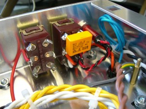
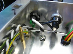
When wiriing the AC from the power cord input it is best to take the safety ground wire directly to its own chassis ground stud with a ring-terminal so that it can’t slip off inadvertantly. The hot wire should be short and go to the back of the fuse holder for additional safety when the fuse is out. A twisted pair can then be made of the fused hot wire and the neutral wire from the power cord and routed up to the front of the chassis where hot and neutral each have a pole on the power switch.
It is traditional to have a MOV (surge varistor) across the AC line at the power switch. I used a special non-shorting capacitor in my build to help surpress any RFI from the line.
Heater AC Wiring
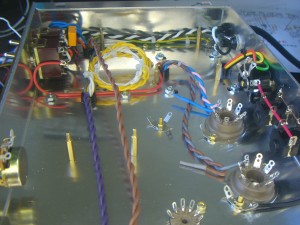
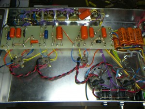
The brown pair from the transformer is routed to the first power tube heater connections and then the heaters for all the other tubes are daisy-chained together from there. I like to ensure that the phase of the heater wires is kept the same on each tube they connect to, but that is subject to varying opinions. In the early build photos there was an error in linking the last power tube to the phase inverter preamp tube… the heater wires were put on the wrong side of the PI tube socket where they would’ve potentially interferred with the PI signals. I’ve included a picture from later in the assembly process to show you the correct orientation of the heater wires… but you already have that figured out from studying the Francesa photos, right?
Output Transformer and Speaker Jack Wiring
The Output Transformer wiring is pretty straight forward. Make sure you align the transformer so that the secondary wires come out near the speaker impedance selector switch as shown. I had a dialogue with Nik to get the transformer colour code and impedances:
- Pink = AN 1 (6.6K-ohm for express)
- Blue = AN 2 (5.2K-ohm for liverpool)
- Red = CT (Center Tap)
- Brown = AN 2 (5.2K for liverpool)
- Grey = AN 1 (6.6K for express)
OT Secondary: (bundle all the wires together with zip-ties, no twisting of the pairs)
- Black =0; routed directly to the speaker jacks and also grounded to the chassis at a power tube socket.
- Green = 4
- Yellow = 8-ohm; later the negative feedback wire will come from the yellow connection on the speaker impedance selector and be routed to the presence potentiometer.
- Orange = 16
I twisted the Pink & Blue together and routed them to one power tube socket (connecting the Pink) and I separately twisted Grey & Brown together and routed them to the other power tube socket, connecting Grey.
Future Considerations
As you complete the preliminary assembly and wiring keep in mind that you will likely want to add a wooden faceplate to the ‘wreck in the future (for tradition’s sake!). This can be a problem with the pilot lamp in particular… the lamp installs from the outside and the nut is internal to the chassis… you need to plan wiring so that you still have room to tighten/loosen the nut and if the pilot light doesn’t slip apart you may need to unsolder the wires and reconnect them once the new faceplate is substituted. If you build without a faceplate you have to plan for the switches and pots to have enough thread depth from the internal lock-nut to accomodate the thickness of the faceplate, nut and washer on the outside. You will also note that the input jack cannot be tightened up properly as it needs a minimum thickness of material in the faceplate. Moot points if you already have your wooden face plate at the start of the project or plan to stick with the plastic one that Ceriatone provides.
Next time we will work on wiring up the power supply board filter capacitors and the power tubes…



February 25th, 2009 at 12:52 am
Hi , I’m Dave From Sherbrooke Quebec….
I’m new in Amp building World , But I’m really passionate and
realist…I have a lot to learn…
I Wish…some day to be able to built my own designe amp.
I see in your web page that you got a schematic layout of the trainwerk that i dont find eany where…can you please tell me where you get it or send me a copy…i will really appreaciate…and if you have the brand of the capacitor I Will appreciate a lot
Best regards
Dave
Thenks
Creepyestday@hotmail.com
February 25th, 2009 at 1:02 am
Hi Dave,
I recommend you sign-up at http://ampgarage.com this is absolutely the best DIY Tube Amp Forum, especially if you are interested in Trainwrecks… you’ll find lots of documentation in the files section there.
Capacitors are also discussed and there are suppliers available that participate regularly on the forum too.
-mark.
February 25th, 2009 at 1:19 am
Thanks Mark !
Can you tell me who supply thr Holy grail filter cap!
Where i can buy it , i cannot find it on the web..or not looking at the good place…
Thanks!
Dave
February 25th, 2009 at 1:35 am
The Holy Grail is Nik’s private label of electrolytic capacitor… so you can get those from Ceriatone as part of a kit… I don’t think they are anything special and you may want a higher quality electrolytic in your build (see ampgarage.com for more suggestions).
The ‘holy grail’ of caps for me is the PS series of Orange drops that I switched to from the Mallory’s that Nik shipped… I think you can get him to substitute orange drops in a kit if you order it, or you can buy them at tubesandmore.com
February 25th, 2009 at 1:47 am
Thanks i will note…i have diffulty to register amp garage because the $%?&/* formate date….
For the cap I like Sprague Atom and SOZO , Mallory a good too
For the tube …Tung-sol in preamp and 6V6 JJ/telsa…
I’m in quest to find a 5Y3 brand …got Svotek and phillip’s..
but i keep searching for upgrade.
November 15th, 2010 at 10:17 pm
In the OT primary wiring, the schematic here: //// http://www.ceriatone.com/images/layoutPic/tWCloneLayout/ExpressionCeriatone.jpg has the OT wiring ////
has the brown and blue connected to the tube sockets. You have the the pink and grey.
Is the schematic wrong?